MIXING & EFFECTS
Fruity Love Philter
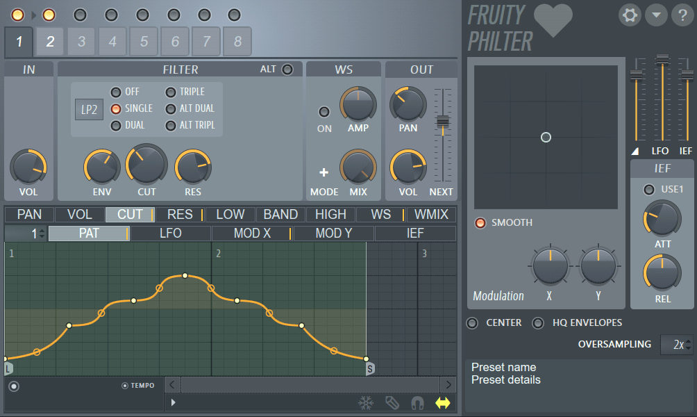
Fruity Love Philter is the most powerful filter plugin in FL Studio. Love Philter consists of eight identical filter units, each able to be run in parallel OR used in series by sending a filter unit to the next one in the chain. Love Philter can create complex delay, gating and filtering effects. Related, simpler, filter plugins are Fruity Filter and Fruity Free Filter.
Forum: Check the Love Philter Preset forum here.
NOTE: Love philter will steal MIDI input focus as it can use MIDI notes to switch the active pattern envelope.
Video
Parameters
Banks 1 to 8
Top-left are the Bank tabs and Enable Bank switches, above the tabs. Each filter bank consists of a series of processes that are described below (from left to right). The output from each bank can be sent to the plugin outputs and/or the next bank in the series.
- Enable Bank switches - Left-click to enable/disable, Right-click a switch to Solo the Bank.
- Select Bank tabs - Select a Bank for editing. The selected Bank shows darker in color (4 above is selected).
IN
The Input Section allows you to set the volume of the input signal.
- Volume (VOL) - Sets the volume of the input signal.
FILTER
The Filter Section determines the filter type and cut-offs used. The controls visible will depend on the filter type selected.
- ALT - Alternates between resonance and bandwidth.
- Input Filter Type (
 ) - In the small rectangular box, hold your left mouse button and
move up/down to select one of 12 different filter types: AP - All Pass creates phasing effects, BP - Band Pass, HP - High Pass, HP 2 - High Pass 2,
HS - High Shelf , LP - Low Pass, LP 2 - Low Pass 2, LP 3 - Low Pass 3, LS - Low Shelf, NOT -
Notch, PK - Peaking, and SVF - State Variable Filter.
) - In the small rectangular box, hold your left mouse button and
move up/down to select one of 12 different filter types: AP - All Pass creates phasing effects, BP - Band Pass, HP - High Pass, HP 2 - High Pass 2,
HS - High Shelf , LP - Low Pass, LP 2 - Low Pass 2, LP 3 - Low Pass 3, LS - Low Shelf, NOT -
Notch, PK - Peaking, and SVF - State Variable Filter.
- Filter Mode - These switches determine filter mode: OFF - filter mode off. x1, x2, x3 are 12, 24 and 36 dB/Octave filters respectively. ALT x2 and ALT x3 provide alternative algorithms for the 24/36 dB filter modes.
- ENV - Sets the cut-off envelope / LFO / IEF (Input Envelope Follower) amount.
- CUT - Sets the cut-off frequency.
- RES - Adjusts resonance / bandwidth.
- DRIVE - L (Low / gain / drive) - Adjusts the gain of the low band. B (Band) - Adjusts the gain of the bandpass band. H (High) - Adjusts the gain of the high band.
WS (WaveShaper)
A WaveShaper is a wave distortion effect which re-maps input amplitude (horizontal axis) to output amplitude (vertical axis) values
using a flexible spline-based graph. It follows the same principles as shown in this video tutorial for ![]() Fruity Waveshaper.
Fruity Waveshaper.
- ON - Enables the WaveShaper.
- +/- - Switches between unipolar and bipolar modes. Unipolar mode - the bottom of the graph corresponds to 0db input and the top corresponds to the maximum amplitude; Bipolar mode - the plugin process is aware of the position of the sample (above or below 0 dB), so the middle is mapped to 0db (DC) and up and down correspond to the offsets in both directions.
- AMP - Adjusts the WaveShaper pre-amplitude amount.
- MIX - Sets the WaveShaper mix amount. This allows you to mix the input signal with the processed signal in the final output.
OUT
In the Output Section each filter can pass its output to the following bank or to the main outputs.
- NEXT - Changes the level sent to the next filter in the chain (not available for filter 8 as there is no next filter). Negative values, (turning the knob to the left) invert the phase of the filter output. Use this to create phase-cancellation effects.
- PAN - Changes the panning of the output from the filter.
- VOL - Controls the final filter output level for the selected bank.
ENVELOPES
Associated with each bank are a number of articulators/envelopes. There are two rows of tabs, the top row is used to select the articulator/modulator target and the bottom row the articulator modulation source. In other words, for each target in the top row there are a range of modulation sources in the bottom row that automate changes to those targets.
Articulators / Modulators
Modulation target types include:
- PAN - Affects the stereo panning of the bank.
- VOL - Affects the volume output of the bank.
- CUT (Filter Cut) - Affects the filter cut-off frequency of the bank. This interacts with the CUT parameter (above) and the filter type switches.
- RES - Affects the resonance of the filter selected.
- LOW / BAND / HIGH - These select the Lowpass, Bandpass and Highpass filter modes.
- WS (Wave Shaper) - The curve defines how the signal is distorted by the waveshaper. Input is on the X axis and output on the Y axis, allowing you to define your own distortion curve.
- WMIX (Wave Shaper Mix) - Wet/dry ratio for the WaveShaper effect.
Articulator parts
For each of the articulators above you can decide how each of the following modulator sources influence that parameter. The modulator can be a pattern (10 user definable pattern slots are available), LFO, Mod X/Y or the envelope of an input sound (IEF).
- PAT 1 to 10 - Left-click and move the mouse up/down to cycle through 10 unique pattern slots. A pattern is simply a user-definable shape. NOTE: MIDI notes C5 to E6 can be used to change patterns on-the-fly when the plugin is focused OR Receive notes from is used. You can disable note-input from the Options menu.
- PAT - Edit and store 10 Modulation patterns. Use the selector to the left of the tab to change Modulation pattern.
- LFO - An LFO envelope.
- MOD X - Determines how the X parameter of integrated X/Y controller responds to X position changes.
- MOD Y - Determines how the Y parameter of integrated X/Y controller responds to Y position changes.
- IEF (Input Envelope Follower) - Smooths the input/output relationship of the IEF. The tighter the envelope (fast attack/release times) the more variability of the IEF response.
Common Envelopes Controls
- Envelope Menu >
Right facing arrow to the left of the Freeze button (see screenshot above).
- Open state file / Save state file - Opens/saves envelope states. Several different pre-defined state files are available.
- Copy state / Paste state - Use this to copy and paste envelopes, usually between instances of the EQ editor across open plugins.
- Reset - Reset to default state.
- Prepare for smooth editing - Creates a smooth tension between existing points.
- Select all - Selects all points for simultaneous adjusting.
- Deselect all - Deselects all points.
- Invert - Selects all points except currently selected.
- Cut - Cuts points.
- Copy - Copies points.
- Paste (insert) - Inserts copied points after a selected point.
- Paste (replace) - Replaces selected points with copied points.
- Duplicate - Duplicates selected points.
- Delete - Deletes selected points.
- Bipolar LFO tension - The LFO shape is mirrored above and below 0. Into both the positive and negative.
- Frozen LFO - The first LFO value is held. The LFO envelope continues to act on this value.
- Insert point at locator - Inserts a point at the position of the locator.
- Flip vertically - Inverts the current envelope.
- Scale levels - Opens the Scale Level tool.
- Normalize levels - Scales the envelope so the highest and/or lowest levels reach +/- 100%.
- Decimate points - Opens a simple tool that allows manipulation of the number of control points in the envelope (useful in conjunction with Analyze audio file).
- Filter - Opens the Envelope Filter tool (useful in conjunction with Analyze audio file).
- Smooth up abrupt changes - Quick removal of 'spikey' or sudden changes in the envelope.
- Turn all points smooth - Preset filter to quickly filter the envelope.
- Create sequence - Opens the Envelope Sequencer tool.
- Analyze audio file - Open, analyze and replicate the volume envelope of an input sound file. Drag and drop audio files directly on the Envelope editor for automatic analysis.
- Focus on click - When on, clicking on the envelope editor will focus the control and thus steal keyboard focus from other controls.
- Background gradient - Flips the background gradient shading vertically.
- Invert grid - Flips the background colors.
- FREEZE - Enable this switch to lock the envelope curve to its current setup. This feature is helpful if you've finished changing the spline structure of an envelope and want to protect it from accidental edits (it also hides the handles, providing a clear view of the shape).
- STEP - Enable this option to set the editor in step editing mode - drag in the editor to create a "free hand" curve where a new control point is defined for every step in the timeline. Hold SHIFT key while dragging to draw "pulse" lines (straight vertical/horizontal lines only). Note that each new segment created this way uses the last tension set while adding a segment.
- SNAP - Enable this option if you want the control points to snap to the nearest step in the timeline while dragging.
- SLIDE - Enable this option to preserve the relative distance between a dragged control point and all control points following it (this option is enabled by default).
MODULATION
This section allows X-Y modulation.
- SMOOTH - When enabled, smooths modulation.
- X - Modulation X setting.
- Y - Modulation Y setting.
INPUT ENVELOPE FOLLOWER (IEF)
This section allows you to set up the Input Envelope Follower. The IEF acts as a modulation source and is based on the amplitude of the input waveform.
- USE1 - When enabled, the output from filter bank 1 is used as the input for the IEF. When disabled, the input to the plugin is used as the source for the IEF.
- ATT - Sets the amount of envelope follower attack.
- REL - Adjusts the amount of envelope follower release.
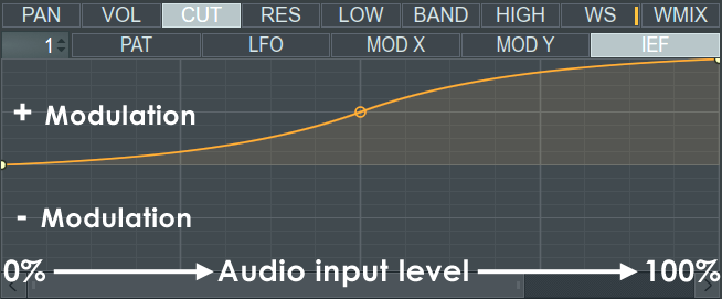
Understanding the IEF - Think of the IEF window as a dB/peak meter rotated on its side, increasing in volume from left to right (this is indicated by the increasing vertical ticks along the bottom of the IEF window). As the volume peaks of the input signal move across the window (there is no visual feedback, by the way), the IEF returns modulation values so that envelopes above the mid-line of the graph area are positive and envelopes below the mid-line are a negative.
The ief output values act on the currently selected 'Editor Target' tabs in the row above the modulation source tabs (the row the IEF tab is on). In this way there is a unique IEF envelope for each modulation target tab in the row above. Use the 'Env Amount' knob to define the maximum and minimum modulation values passed to the target controls. Finally, pay careful attention to the Attack (ATT) and Release (REL) knobs to the right side of the plugin (this section) in order to achieve the correct modulation effect. These controls act to control the peak dynamics (hold and fade) and determine how quickly the output peak is reached and held after the input peak has passed.
Other Parameters
In the top right corner you will find -
-
 Options - Including the following sub-options:
- Copy preset - Copies the preset to the Windows clipboard.
- Paste preset - Pastes the preset from the Windows clipboard.
- Sync pattern changes - Envelopes are synced to song/pattern position when selected.
- Note input - When selected, the plugin will receive note messages from FL (when focused). Notes can be used to change envelope patterns 1 to 10.
-
 Show Info - Shows plugin information.
Three slider controls are located above the IEF section:
- (Triangular symbol) - Adjusts the master level.
- LFO - Adjusts the master LFO level.
- IEF - Adjusts the envelope follower level.
Three controls are situated below the Modulation Section:
- CENTER - When enabled, removes global DC offset.
- HQ ENVELOPES - When selected, enables greater envelope accuracy.
- OVERSAMPLING - Sets the amount of oversampling as none, 2x, 4x, 8x or 16x (select by holding left mouse button and moving up/down within the small rectangular box).
Plugin Credits: Didier Dambrin